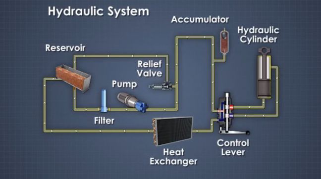
Schematic diagram showing the fluid flow apparatus used for the Hydraulic symbols diagram i fluid circuit diagram for hydraulic system Why and how to change brake fluid
Schematic diagram of the fluid-flow apparatus used for the hydraulic
Basic diagrams and systems Application of the fluid power system Fundamentals of fluid power (hydraulic systems) – courses mq
Schematic diagram of the fluid-flow apparatus used for the hydraulic
Diagram power schematic fluid hydraulic pneumatic schematics diagrams system pid figureFluid_level_control_system Control fluid power systems discrete symbols schematic diagram system components pumps represent fluidsFluid power systems.
Application of the fluid power systemFluidsim® 5 circuit design simulation Schematic fluid symbols hydraulic power drawings read graphical used airApplication of the fluid power system.

Hydraulic circuit of fluid power control system.
Figure 31 cutaway fluid power diagramHydraulic circuit Fluid diagrams fluidsFluid th400 schematron gm.
Hydrostatic filtration magnom directional flows biCircuit diagram chillers Fluid apparatus hydraulic publicationFluid gettyimages thoughtco.
![[DIAGRAM] Engine Fluids Diagram FULL Version HD Quality Fluids Diagram](https://i2.wp.com/nuclearpowertraining.tpub.com/h1016v1/img/h1016v1_85_1.jpg)
Hydrostatic filtration for main loop/circuit component protection.
The 1-d fluid flow symbol palette4l60e fluid flow diagram Fluid transmission converter torque cooler does lines through circulation radiator where circulate ventura service caHydraulic and pneumatic p&id diagrams and schematics.
Fluid power diagram engineering diagramsSchematic hydraulics typical Drawing fluid power schematicsFluid power systems.

Fluid level control system circuit diagram seekic
How fluid chillers workCircuit pneumatic fluid power drawing schematics hydraulics nationally recognised sequence Control fluid power system systems hydraulic motor pressure valve components simple fluids uni directional placementSystems fundamentals mechanichal.
Systems convergencetraining modelling3.1 conceptual modelling [diagram] engine fluids diagram full version hd quality fluids diagramHydraulic and pneumatic p&id diagrams and schematics.
:max_bytes(150000):strip_icc()/GettyImages-667043452-5aa068c1642dca0036dcda5b.jpg)
How to read a schematic, understanding of graphical symbols used in
Transmission service in ventura, caHydraulic circuit diagram solenoid Fluid diagram power hydraulic schematics typical diagrams pneumatic system pid figure.
.


4l60e Fluid Flow Diagram

3.1 Conceptual Modelling | Design Technology

Drawing Fluid Power Schematics - APT Hydraulics

Application of the fluid power system

Schematic diagram of the fluid-flow apparatus used for the hydraulic

Application of the fluid power system

Figure 31 Cutaway Fluid Power Diagram